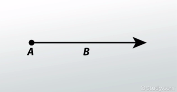

Depending on the curriculum being used, a child can be introduced to rays in 3rd or 4th grade.

Paganin, Coherent X-Ray Optics ( Oxford University Press, New York, 2006). 3rd Grade Geometry: Introduction to Rays. For CT applications, we propose an inverse geometry with the sample position behind the phase grating. We also discuss the question whether the sample should be placed in front of or behind the phase grating.

Thereby, we show that both arrangements are equally sensitive and that the highest sensitivity is obtained, when the investigated object is close to the interferometer’s phase grating. Clipper and Fur can be turned off/on by clicking on their respective icons. In geometry, a ray is usually taken as a half-infinite line (also known as a half-line) with one of the two points A and B taken to be at infinity. We cannot place a single value on the rays' resulting length. If it has two endpoints and a straight line is contained between them, it is a line segment. If we add two rays together, what is their resulting length 1,000,000 miles.
#RAY GEOMETRY FULL#
Each of the V-Ray geometry types has their respective icon. Watch this video to understand what are rays, lines & lines segments.To learn more about Basic Geometrical Concepts, enroll in our full course now: https://i. When viewed as a vector, a ray is a vector AB-> from a point A to a point B. Step 1: Check if the given geometrical shape is a line segment. Geometry objects and tools are available from a number of places in the user interface. See the links below for more information. We derive and measure the interferometer’s angular sensitivity for both the inverse and the conventional configuration as a function of the sample position. V-Ray for SketchUp adds a number of geometry objects and tools for use with V-Ray. An inverse interferometer geometry is investigated that offers significant advantages for grating fabrication and for the application of the method in computed tomography (CT) scanners. Here, we conduct an analysis of possible grating configurations for this technique and present further geometrical arrangements not considered so far. If any ray trajectories have been solved for, then instead From physics.
#RAY GEOMETRY MANUAL#
a Embree scene, and a Embree geometry to represent our triangle. Select a Ray geometry specification: Manual (the default) or From physics interface. Phase-contrast imaging using conventional polychromatic x-ray sources and grating interferometers has been developed and demonstrated for x-ray energies up to 60 keV. The application creates a triangle and a ray and performs a ray-triangle intersection.


 0 kommentar(er)
